Spaceport America Cup
To continue to test our abilities, we compete in the internationally recognized Spaceport America Cup (SA Cup), hosted by the Experimental Sounding Rocket Association (ESRA). This year, we plan on entering the 30,000 ft Commercial Off-The-Shelf (COTS) competition. Here, the challenge is to get as close to our target altitude as possible. It’s a major challenge, requiring the construction of our most difficult to manufacture, fastest moving, heaviest rocket to an altitude we’ve never hit before.
SA Cup 2023-2024 Rocket
Design and development of our SA Cup 2023-24 rocket is underway! We intend on competing in the 30K COTS category, integrating new manufacturing and aerostructure technologies along the way. We look forward to providing newsletter and social media updates of our progress throughout the year.
Previous Years
2022-23

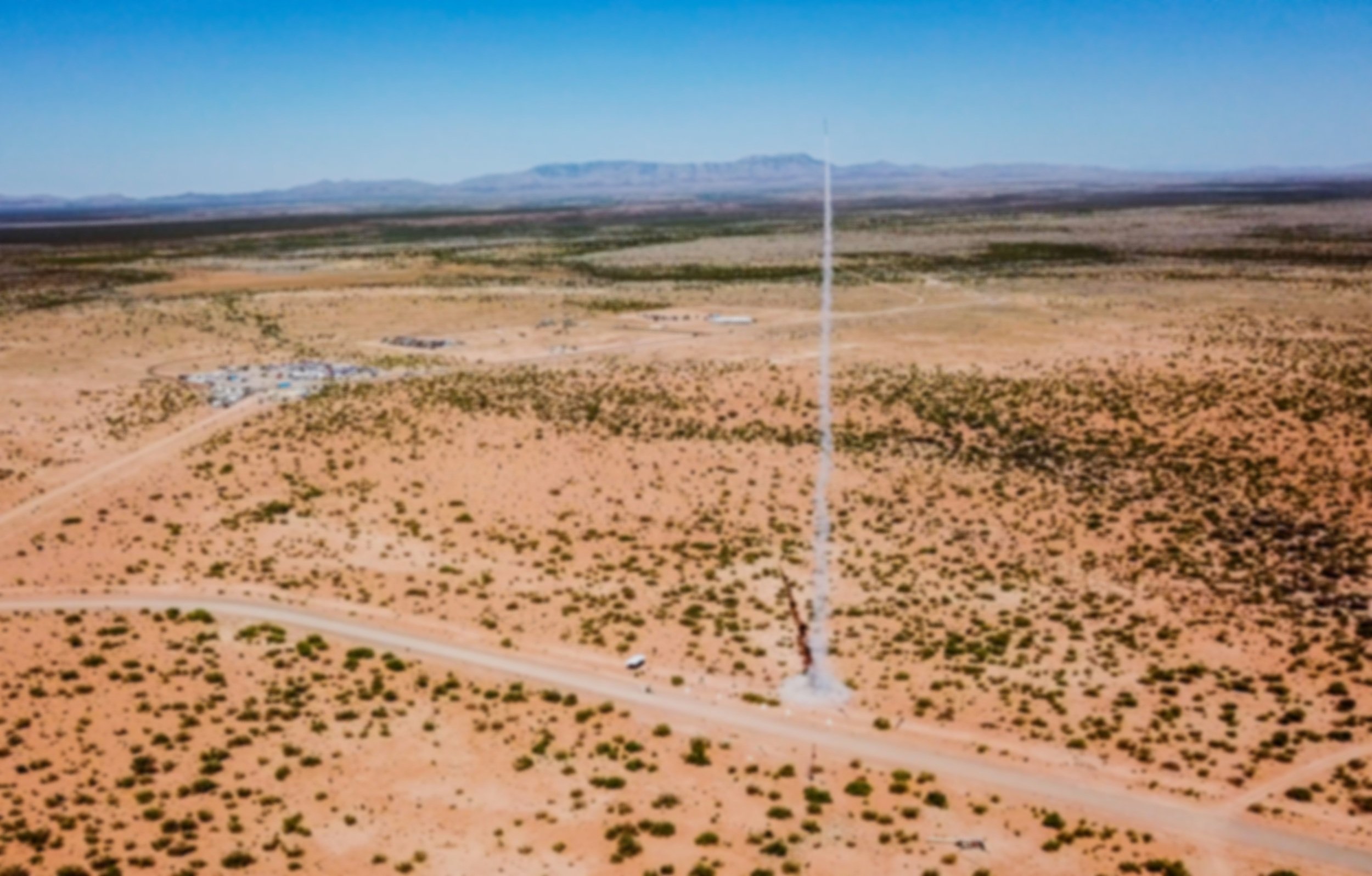
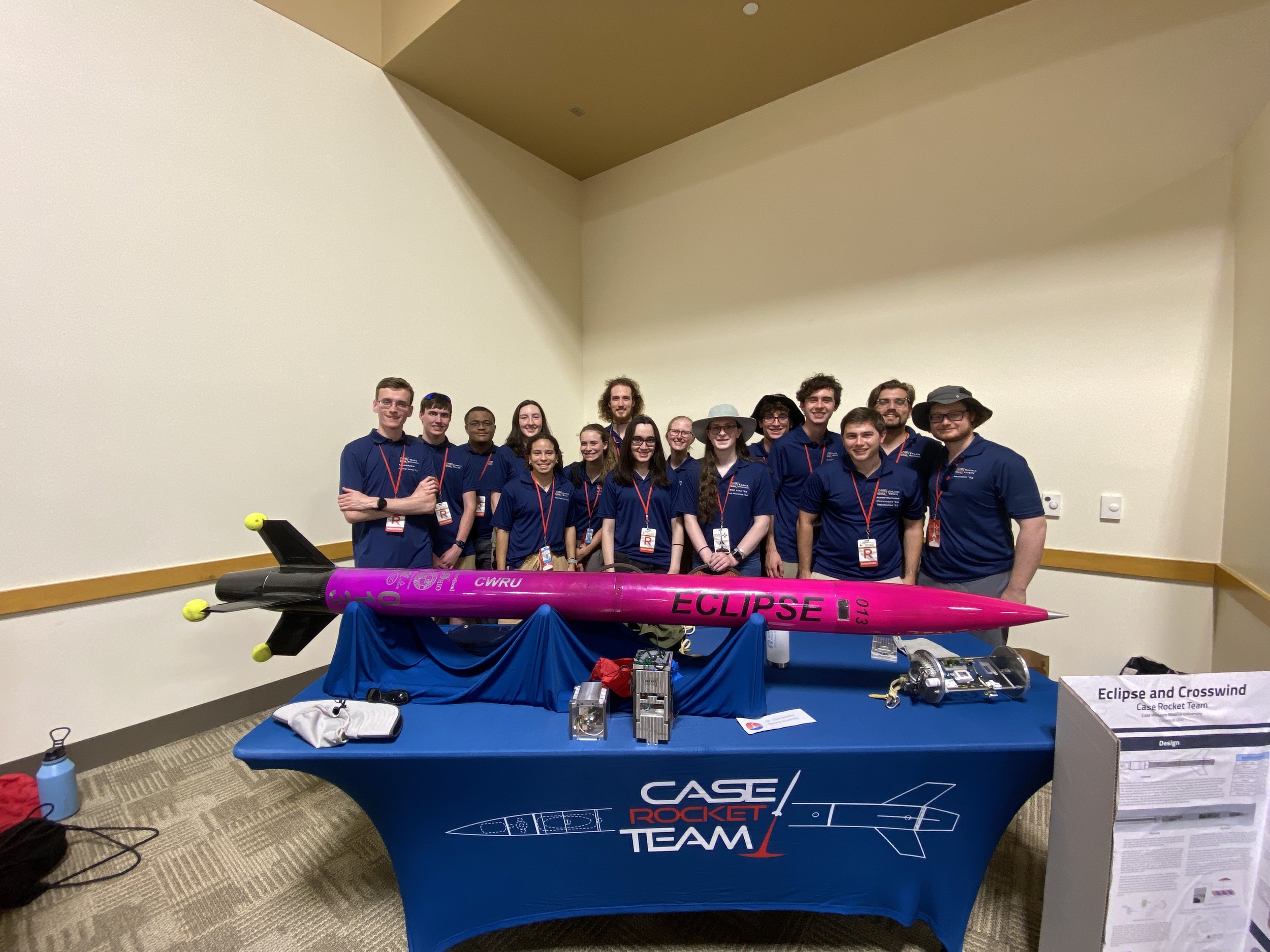
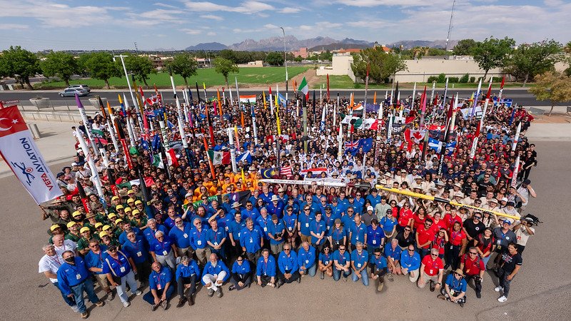
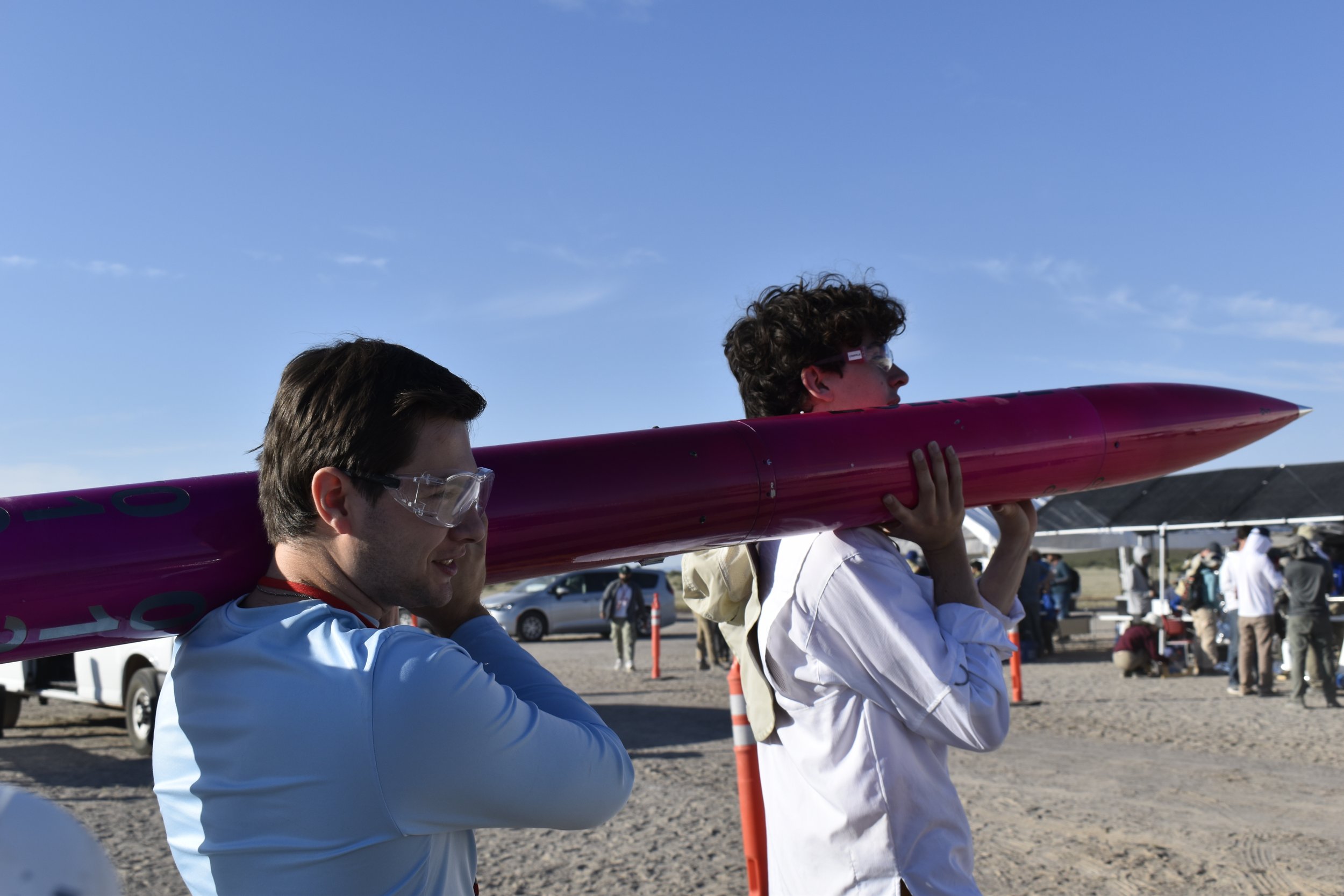
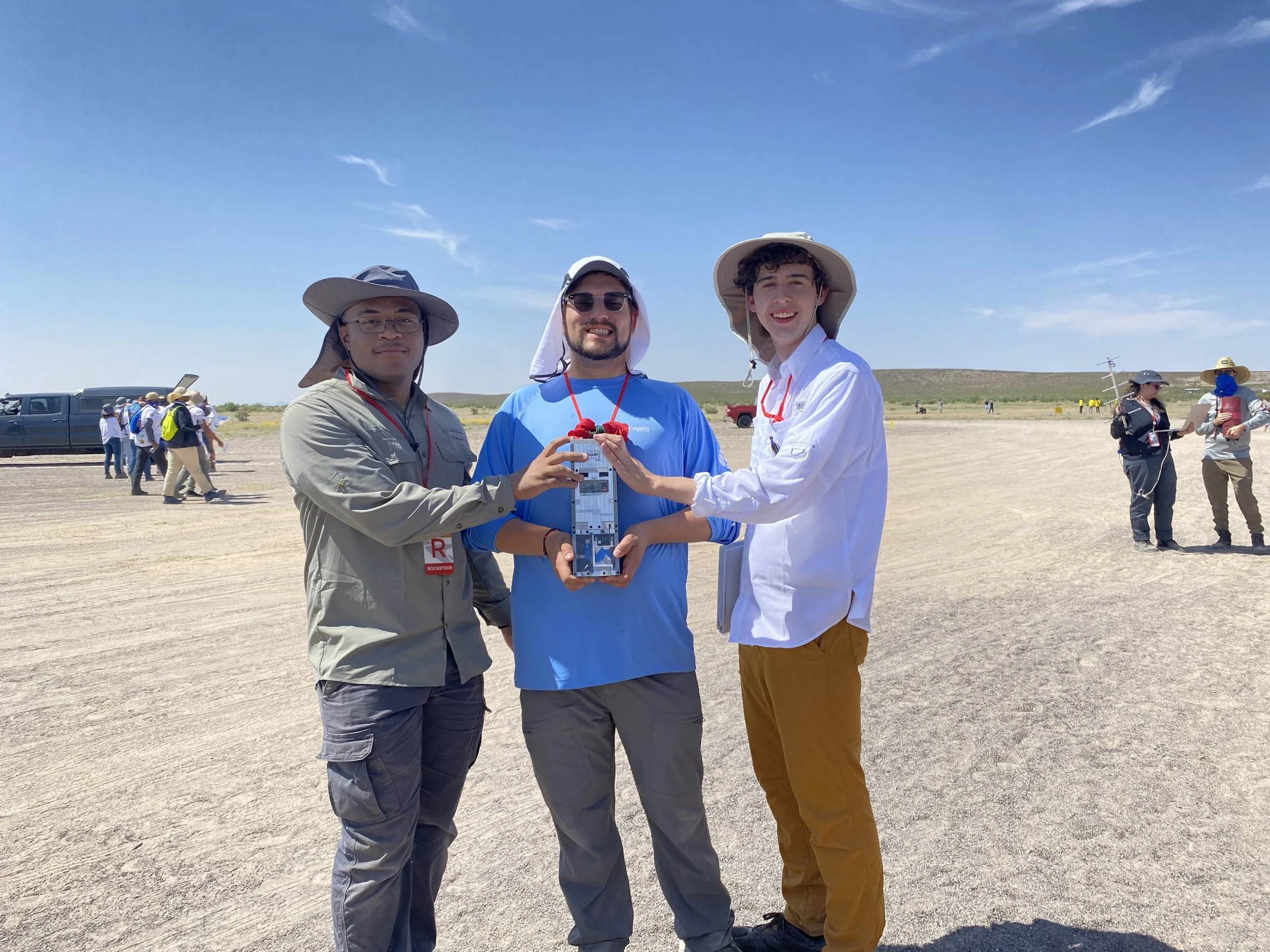
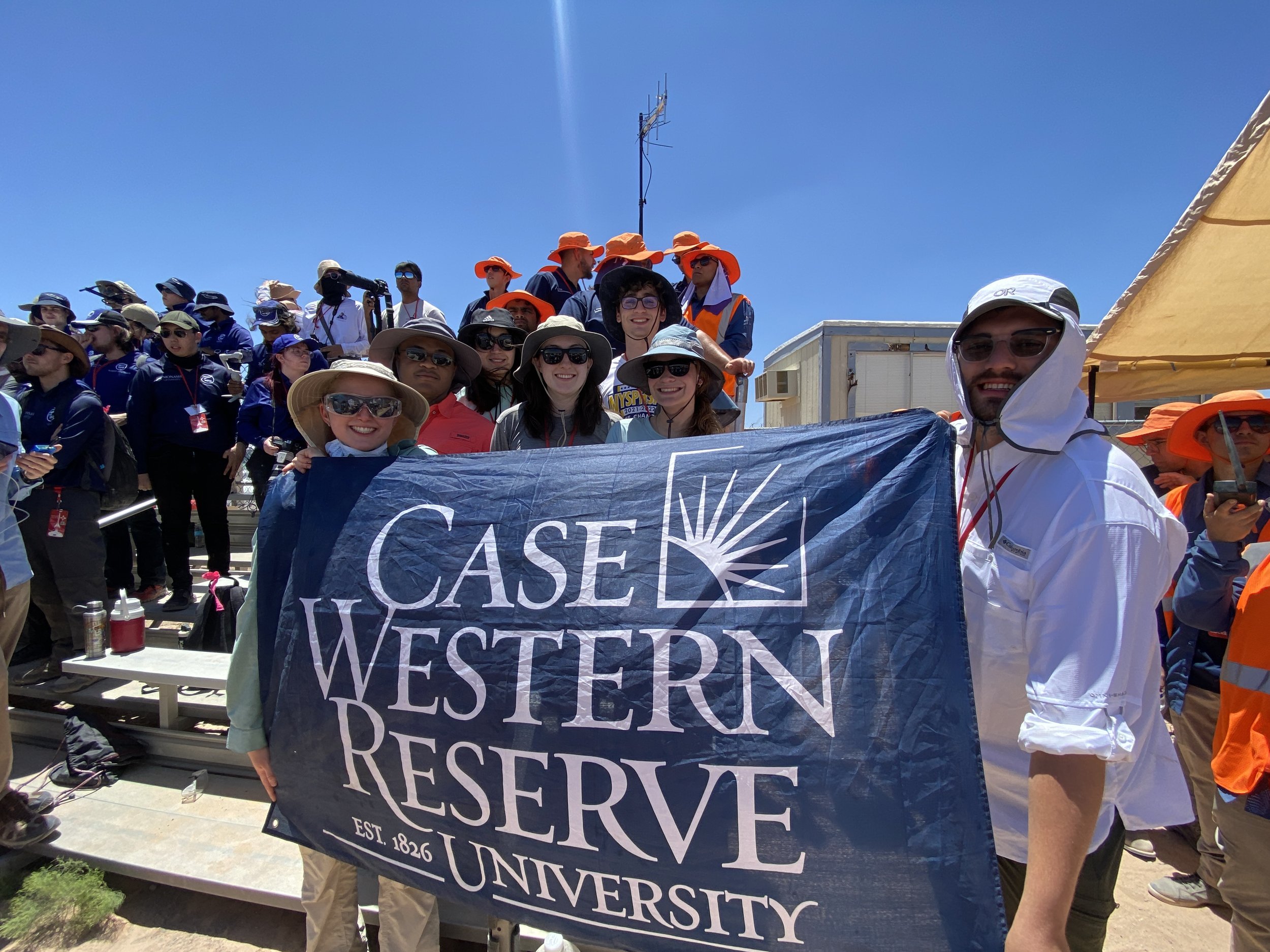
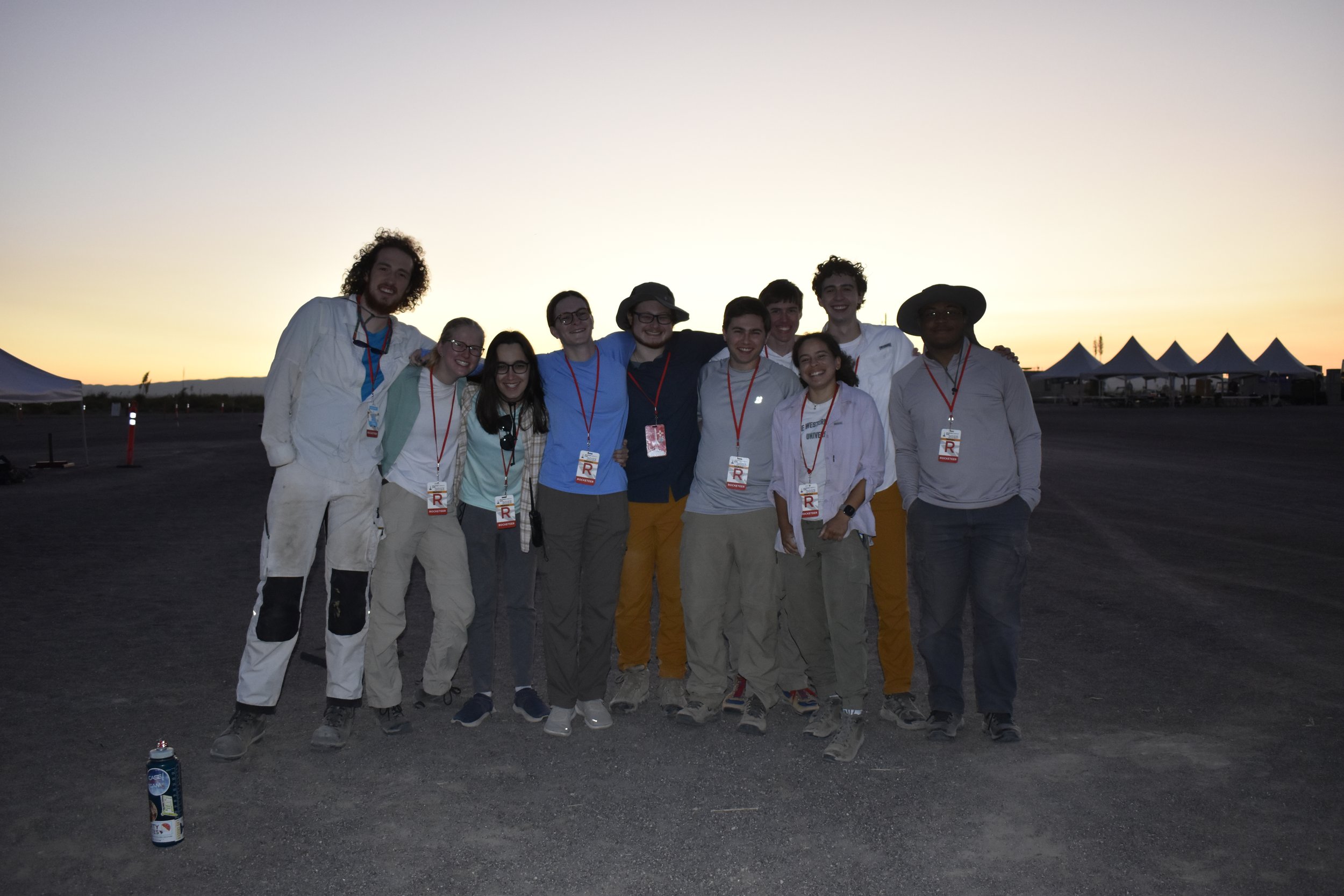
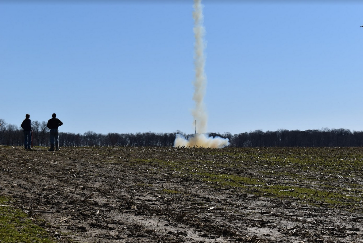
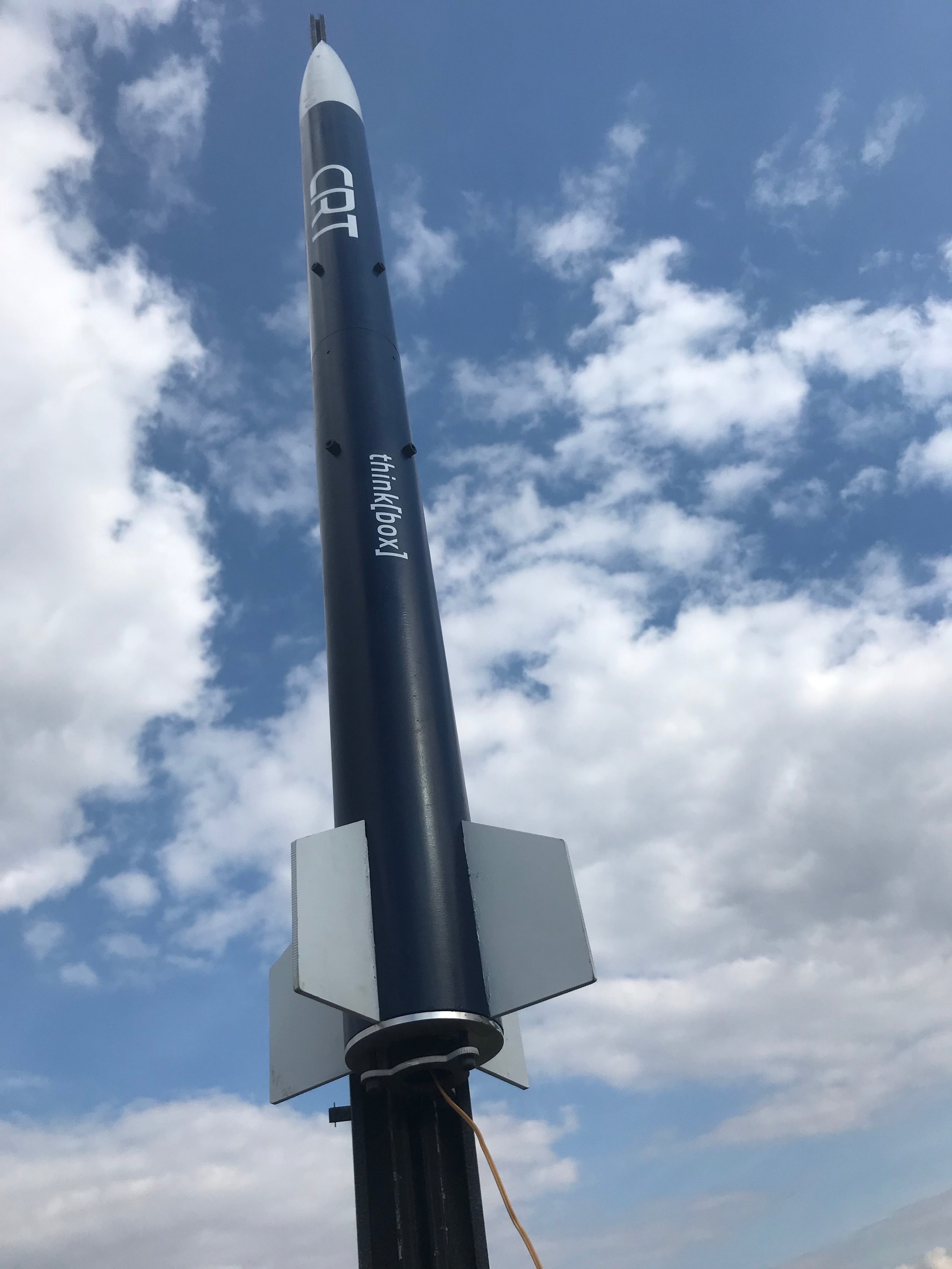
After a strong first place performance in the 10K COTS category of the 2022 Spaceport America Cup, the Case Rocket Team set their sights on the 30K COTS category for the first time in this year's competition. After months of tireless designing, manufacturing, and planning, the team arrived in Las Cruces, New Mexico with a completed rocket and payload, Eclipse and Crosswind respectively, but had not conducted a test launch due to Ohio weather conditions. Upon arriving in the desert, we encountered extreme winds that created unforeseen adversity and rocket repairs. The team persevered, gaining recognition from ESRA and the competition organizers. After rocket and motor modifications, Eclipse and Crosswind successfully launched to an altitude of over 23,500 ft, establishing a new team altitude record. Our cumulative score also earned us an 8th place finish in the 30K COTS category. We created tremendous memories, met peers from around the world, and connected with a variety of top aerospace companies and professionals. We would like to thank the university for all its support, and we look forward to competing in next year's competition!
2021-2022

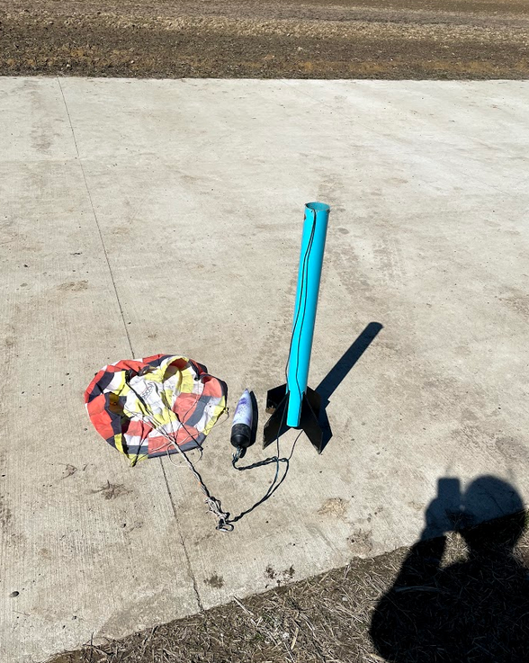
Case Rocket Team earned 1st place among U.S. teams and 2nd internationally at the Intercollegiate Rocket Engineering Competition (IREC). This is the first time CRT launched a physical rocket to compete with the more than 150 international teams at IREC, also coming home with 1st in our category! After nearly two years of pandemic obstacles, we are incredibly happy with the performance of the most advanced rocket the team has designed. The goal of the competition is to launch a rocket to a target altitude, in our category 10,000 ft AGL, as close as possible. We came within 102 feet of that altitude, in the top 99th percentile of teams in terms of accuracy. Additionally, we had a fully successful flight test, with no failures in any critical systems, allowing for a full recovery of the rocket intact. The goal of the rocket, in addition to the altitude target, was to deploy a separately recovered technical payload and nose cone. The payload was a flight test at an altitude of a parafoil recovery method the team hopes to implement further to allow for fully autonomous recovery of a scientific package.
2020-2021
This was an interesting year full of novel challenges. The COVID-19 Pandemic made in-person meetings impossible, manufacturing extremely difficult, and new-member inclusion complex. It was also our first time attending a SA competition! Despite all of these, the team was able to manufacture two 4” test rockets, Spargarite and Once More, and made extensive design improvements throughout the year. Late in the year, Spaceport America decided to host the competition virtually for the safety of all of the teams, so we got working on our competition paper. For our work on the parafoil-guided payload recovery system, we were selected for a podium session. At the end of the competition, we were awarded 3rd place in the 10,000ft COTS all propulsion types competition and 9th place overall!
NAR Certifications
All members have the opportunity to participate in a certification program by the National Association of Rocketry (NAR). This is perfect for those who wish to build and fly High Power Rockets (HPR). HPR Level 1 Certification allows the purchase and use of H and I impulse class motors while Level 2 Certification allows the purchase and use of J, K and L impulse class motors. Prospective members should not be discouraged by this task. Senior members will walk through the process and will provide one on one instruction if needed.
During the 2020-2021 year, 3 members attempted Level 1 HPR certification and 3 members attempted Level 2 HPR certification. All members passed (some extra attempts were needed) and are looking forward to their next certification level!
Level 1 Certification Rocket Diagram


Current Projects
We are constantly looking to push our team’s knowledge to its limits and learn new things. Every year, we work on a number of projects to test new ideas and improve our existing technology. This year, we worked hard on three major projects: Fiberglass Manufacturing, Airbrakes, and Live Streaming Video.
Airbrakes
Goal: What is the project supposed to do?
To achieve as close to 10,000ft as possible for the SA Cup, we experimented with airbrakes: flaps that deploy from the rocket to increase the drag, a Variable Actuation Apogee Adjustment Module (V.A.A.A.M). The flaps help to slow down the rocket as it reaches within 5% of a target apogee. As the rocket approaches apogee, V.A.A.A.M will use real-time telemetry to monitor the flight and to continuously recalculate the target altitude. The recalculated target altitude will be used to adjust the angle of flap deployment accordingly.
V.A.A.A.M is currently being tested on the rocket an as-yet-unnamed airbrakes test rocket.
Concept: How does your machine function?
Software simulation process:

Hardware System
Deployment Mechanism:


For deployment, the stepper motor will move the linear carriage along a lead screw, which will move the actuation tubing up and down. On the other end of the actuation tubing, the hinges move out of the airframe, deploying the flaps.


Timeline: What has happened on the project?
Members of Rocket Team started working on an airbrakes system in 2015 for the Battle of the Rockets 2016. Instead of using a stepper motor, the original design used a CO2 cartridge of compressed air to deploy the flaps. The CO2 cartridge would release pressure through a flow control value, which would deploy the flaps.


In 2017, the team moved into experimenting with a simple rocket stability system. The system used wheels, referred to as “Rollerons,” that were attached to the tips of the fins, and spun up as air flows over the rocket.
In 2019, the airbrakes flap idea was picked back up again and started working on the current design.
Status: Current Status, Needs for the Future, Etc.
Currently, the V.A.A.A.M is ready to be manufactured and installed into our new airbrakes test rocket. We look forward to many test flights to come so we can improve our design and record data to understand how the function of the V.A.A.A.M can be enhanced.
Past Projects
We also want to showcase our past work. These are the projects that helped to expand the team’s knowledge and push us to do more.
Live Streaming Video (Aurora, Horus)
Team Lead: Vincent Portelli, Letica Dornfeld
A challenge our Electronics team worked on was Live Streaming Video. The SA Cup offered bonus points for live video and we felt we were up to the task.
Here was the results of our first in-flight test of the camera system.
Fiberglass Manufacturing (Spartan I)
Team Leads: Alex Brandt and Jonah Sachs-Wetstone
Our team’s big research focus switching between Battle of the Rockets and the Spaceport America Cup was to improve our ability to manufacture fiberglass structures. This was primarily done by experimenting with how to tool fiberglass and fiberglassing various components.
We first looked into fiberglassing a fin. This was designed to be a wood-core with fiberglass layers wrapped around it. Our test articles passed strength and durability tests, but bubbling and delamination made us concerned over its usability.
We then looked into a full rocket design to test various fiberglass manufacturing methods. This allowed us to test how best to make and machine flat components, such as bulkheads and fins, and cylindrical components, such as our motor and body tubes. Our flat components were manufactured from a single sheet of fiberglass using our machine shop’s OMAX Waterjet. The intense pressure cut through the part well, but every time it pierced the surface, we observed delamination and bubbling. Moving the lead-in off of the part made the cuts clean on our second test run.
The cylindrical components needed many small holes and slots that had to be relatively precise to be flight-worthy. These were primarily done using our machine shop’s mill machine with a part to hold the tube in place and rotate it through 90 degrees. After getting the hang of it’s operation, the actual manufacturing was relative easy. The larger problem was containing the fiberglass dust. Unlike the Waterjet, in which the water covering the part keeps the dust contained, the tubes cut on the mill had to be covered completely. Our team members wore fiberglass-rated face masks and all work was done after-hours in the machine shop.
Inspecting the rocket after final assembly, we observed no major cracks or damages and confirmed proper fin allignment. This made us confident that we were flight-ready. Spartan I was launched to an altitude of 3,300 ft using a J270 motor. The fiberglass structure preformed nominally.
After launch, we changed our fin design to more closely follow our previous research on fiberglassing a core fin, using balsa wood. Instead of just fiberglassing the fin, however, we fiberglassed the fins tip-to-tip. This means that fiberglass was laid from the tip of one fin across the body to tube to the tip of the other. This change created a strong difference in durability and rigidity, giving us the confidence to use in on our final rocket.
Rolleron
Team Lead: Tobias Behrens
Used on Sidewinder missiles, the Rolleron concept is a passive stabilization technique that involves wheels mounted on the trailing edge of the rocket's fins. In flight, the wheels spin to create a gyroscopic effect that keeps the rocket on a desired flight path. Exploration of this concept involves fabrication of multiple wheel designs and a test stand. After ground tests, a prototype rocket will be manufactured for flight tests. A modular rocket design will allow easy instillation of the different wheel designs and a regular fin to act as the control. Computer simulations and data acquisition from test launches will help determine the effectiveness of a specific wheel design.


Boosted Dart
Team Lead: Layee Chau
The Boosted Dart is CRT's largest endeavor yet! Continuing on last year's developments, the Boosted Dart concept is a two stage rocket with an unpowered second stage, the Dart. After motor burnout, the booster stage will separate from the dart due to its higher drag coefficient and with the assistance of pneumatics. The dart will coast up to a higher altitude and deploy its non-pyrotechnic recovery system at apogee. This is unique in that the drogue and main parachutes will deploy from the tail of the dart using pneumatics for ejection (not an explosive charge).
Measuring 10 feet, 9 inches tall with a maximum diameter of 7.5 inches, this rocket will be capable of carrying a 10 pound payload up to 10,000 feet using an M impulse class motor. Additionally, the dart includes Air Brakes for accurate altitude control. This allows for high altitude and even microgravity experiments thanks to the recovery system deployment method.

Boosted Dart Rocket Diagram

Dart Diagram
This project would not have been possible without notable contributions of the following individuals:
Ben Ault, Tyler Bauer, Allyson Beach, and Alex Luck
Target Altitude
Team Lead: Tobias Behrens
The objective of the Target Altitude competition was to build a launch a rocket to 1,213ft using no larger than a G class motor. The altitude difference from 1,213ft is used for scoring where the lowest score wins. Three attempts are allowed where the two best scores are added together for the final score for the event. This task is approached by calculating the appropriate weight of the rocket based on thrust provided by the motor and adjusting the rocket's weight according to the target height. Computer simulation and testing provided the team with the information needed to reach the target altitude.

Target Altitude Rocket Diagram

Target Altitude Rocket Model
Planetary Lander
Electronics Lead: Justin Green
Mechanical Lead: Alex Brandt
The objective of the Planetary Lander event was to launch a rocket above a predetermined height and deploy a planetary lander. The team needs to design a lander capable of orienting itself upright after landing and transmit telemetry data to a ground station. In order to bring the rocket to the ground safely we designed it to deploy its own parachute separate from the rocket parachute. Then, when just above the ground, the parachute would detach from the rover, allowing it to maneuver.

Planetary Lander Rocket Diagram

Lander, Exploded View

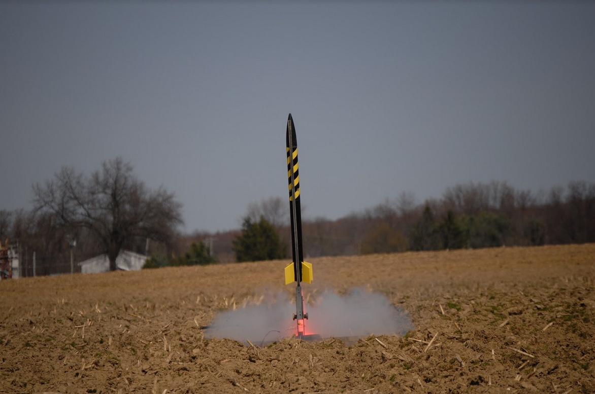
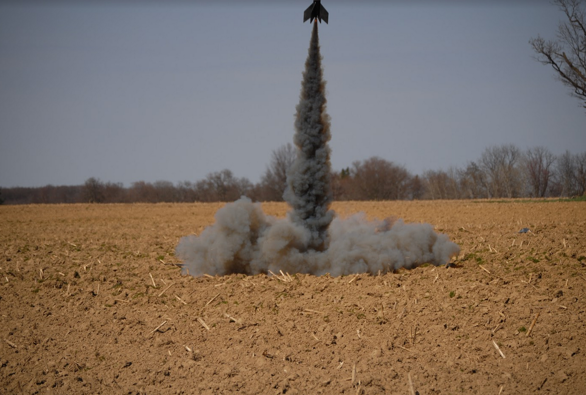
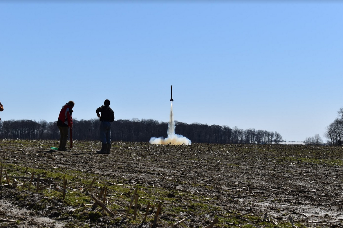
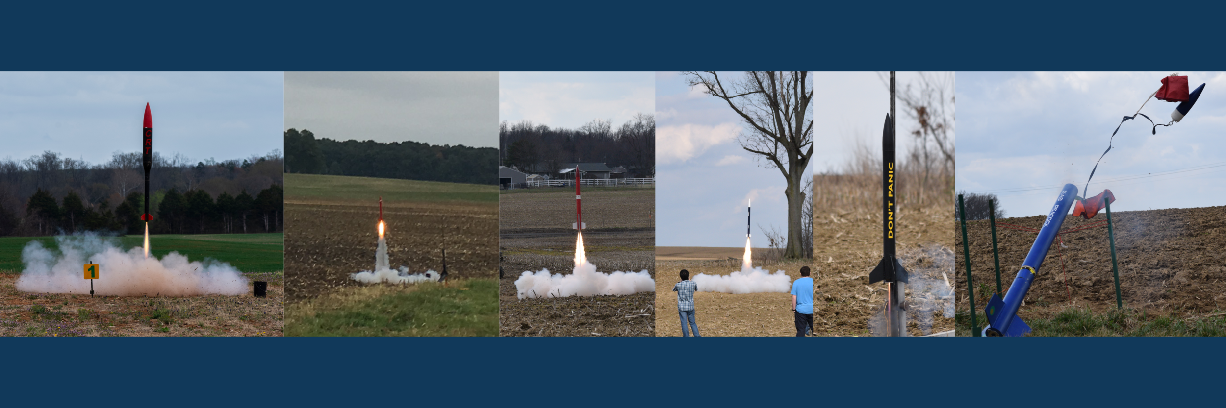
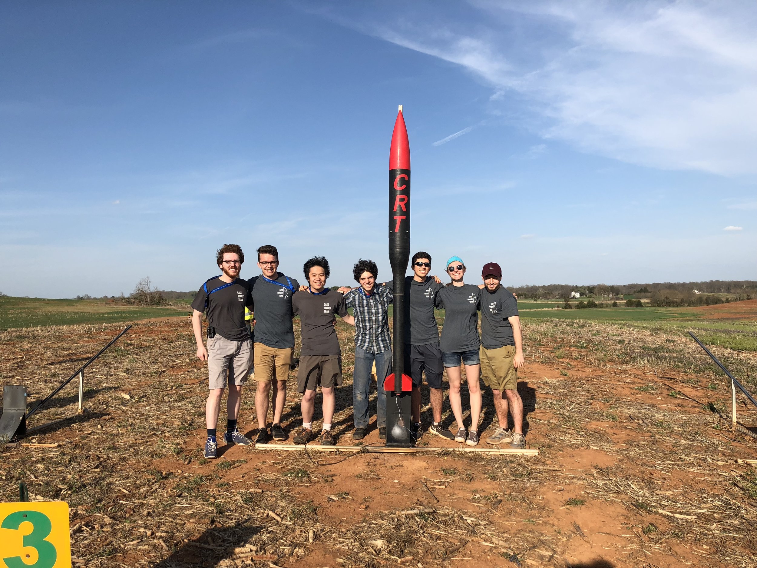
The final rocket (Phoenix) in action!